Restoring an Acorn A5000 after a battery leak
With older computers that are fitted with a battery backed real time clock (RTC) circuit, it's quite common these days to find that the computer has failed whilst in storage. The reason for this failure is a leaking rechargeable battery.
In the photo below, you can see the original battery as fitted to an A5000 which was manufactured in 1992. The battery has leaked extensively around the area where the battery is fitted corroding tracks and damaging the PCB.
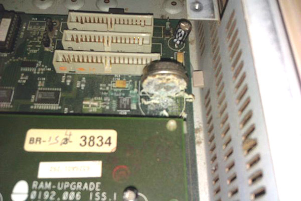
Picture copyright Tautology
Diagnosing the fault
Although a visual check of the battery and motherboard make it pretty obvious that there is damage to the machine and this is the likely reason for it not booting, RISC OS is intelligent enough to indicate many different states and faults by way of flashing the floppy drive in a sequence of short and long flashes.
The floppy drive access light flashing sequence can be noted down and converted into a number which can then be translated into a set of messages using the Acorn Power On Self Test documentation and the full status and fault code list for use with RISC OS 3.x can be seen below:
Status Codes:
| 00000001 | Self-test due to power on |
| 00000002 | Self-test due to interface hardware |
| 00000004 | Self-test due to test link |
| 00000008 | Long memory test performed |
| 00000010 | ARM 3 fitted |
| 00000020 | Long memory test disabled |
| 00000040 | PC-style IO world detected |
| 00000080 | VRAM detected |
Fault Codes:
| 00000100 | CMOS RAM checksum error |
| 00000200 | ROM failed checksum test |
| 00000400 | MEMC CAM mapping failed |
| 00000800 | MEMC protection failed |
| 00001000 | IOC register test failed |
| 00004000 | VIDC Virq (Video Interrupt) timing failed |
| 00008000 | VIDC Sirq (Sound Interrupt) timing failed |
| 00010000 | CMOS unreadable |
| 00020000 | RAM control line failure |
| 00040000 | Long RAM test failure |
The POST status value which this A5000 was reporting was &10059 which is made up of status codes 1, 8, 10, 40 and the fault code 10000. The fault code indicated that there were no other faults with the A5000 which was good news.
Repairing the fault
Stage 1 - Remove the battery, clean the PCB and check for continuity
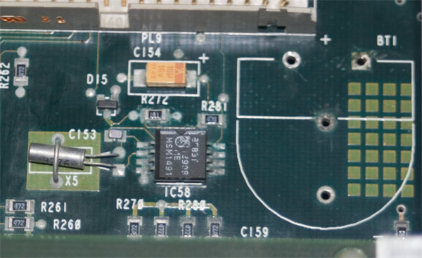
The first thing to do when encountering a battery that has leaked is to remove it, clean the PCB and evaluate the damage to see if it can be repaired. Looking at the photo below, the damage to the PCB doesn't look quite as bad once the battery residue has been removed and cleaned up.
After the PCB has been cleaned, it's important to check all the tracks in the area surrounding the battery that may have been damaged for continuity whilst referring to the circuit board schematic. A simple multimeter with a continuity checking facility can be used to test the tracks by placing the probes at either end of the track.
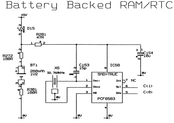
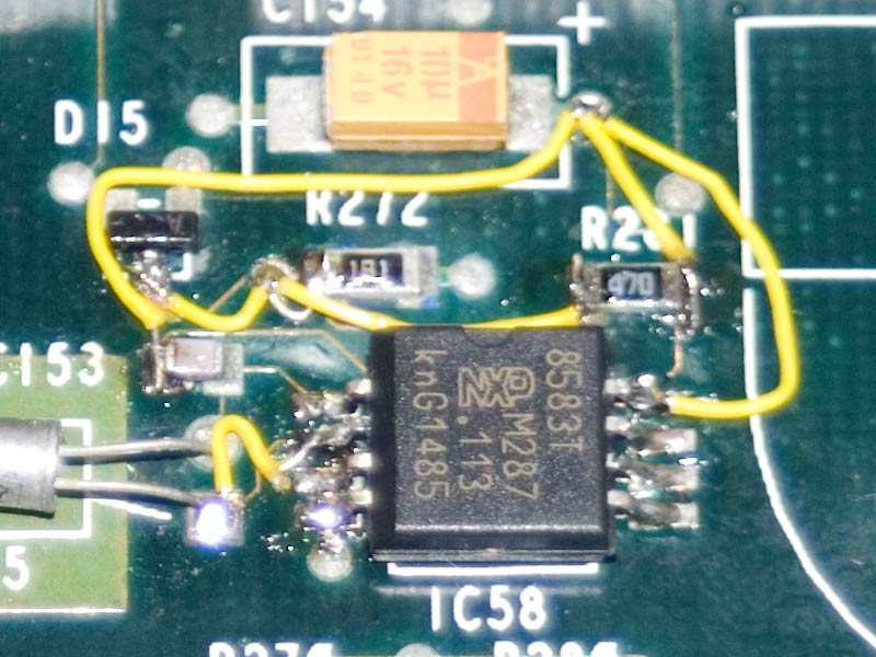
When continuity testing this particular board, the tracks linking D15 to R272, R272 to R281, R281 to pad 8, R281 to C154 and pad 8 to C153 were found to be damaged. As the IDE connector had also been damaged, it was removed and the continuity of the surrounding tracks was checked more easily.
Finally, it's worth checking the tracks on the underside of the PCB if any exist. In this case, all the tracks that connect to the IDE socket and the tracks on the underside of the PCB had survived.
Stage 2 - Remove the RTC CMOS chip (if required)
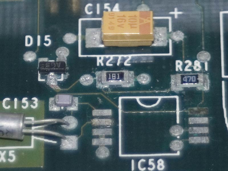
If the CMOS chip has been damaged by the battery leak then it must be removed. Due to the alkali nature of the chemicals released by the battery, some of the surface mount pads may lift even when great care is taken with removing the chip. As you can see from the photo, pad 8 lifted from the PCB and subsequently, pad two also became dislodged during the cleaning and prep work for making the repair.
To remove the chip, use a good flux pen and some Soldamop to remove the solder, after which the chip can be lifted clear of the circuit.
Stage 3 - Repair circuit where required
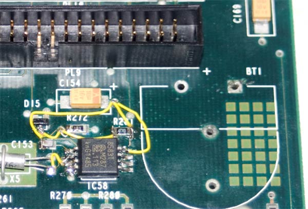
Using the information determined by the continuity checks in stage two, any tracks that have been identified as broken must be repaired. I used some 30awg Kynar wrapping wire to replace the broken tracks and restore continuity of the circuit as can be seen in the photo below. To make life easier, I've used three of the through hole connections to connect to the known working points on the PCB thereby reducing the amount of surface mount soldering required to effect the repair. You can also see the new 40-pin IDE socket that replaced the original damaged socket.
Once the wiring has been fitted, the continuity must be checked again to ensure there are no faults or shorts. The last thing we want to do is cause more damage to the circuit.
At this stage once the continuity has been checked and verified as sound, it's possible to test the CMOS circuitry by powering the computer up and seeing if it boots correctly. As the CMOS chip will be at best, full of random data it will need to be reset by pressing and holding the DELETE key down whilst the machine is powered on for the first time. This process loads system default settings into the CMOS chip from the RISC OS ROMs. Thankfully, my solder work was up to the job and the A5000 booted up on the first attempt.
Stage 4 - Fit a new battery
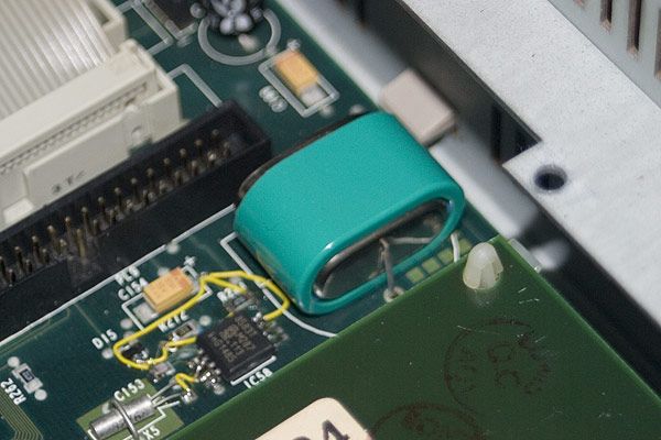
As with all Acorn computers that use a PCF8583 CMOS RTC, the choice of battery that can be fitted is quite wide. I tend to fit Varta Mempac 3/V150H batteries as they are a perfect fit on the Acorn motherboards and are well within the voltage range specified by the PCF8583 chip. Once the battery is fitted, the computer needs to be left on for eight to twelve hours in order that the battery charges sufficiently to hold the CMOS settings when powered down for long periods.
Stage 5 - Test the CMOS data retention
So with the solder work complete, all the tracks repaired and a battery fitted and charged, it's time to see if all the repair work has been 100% successful by powering the computer down for a couple of hours before powering it back up again. If it's worked, the time should be correct and the system settings should all be as they were when powered down.
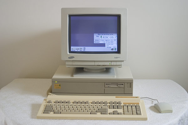
Success! A fully working A5000!
Fixing an A5000 with more damage
Where there is more damage to the motherboard resulting in an in-situ fix being impossible, the CMOS/RTC circuit is straightforward enough to allow it to be re-created on veroboard and connected to known good points on the motherboard by an umbilical cable as can be seen in the images below.
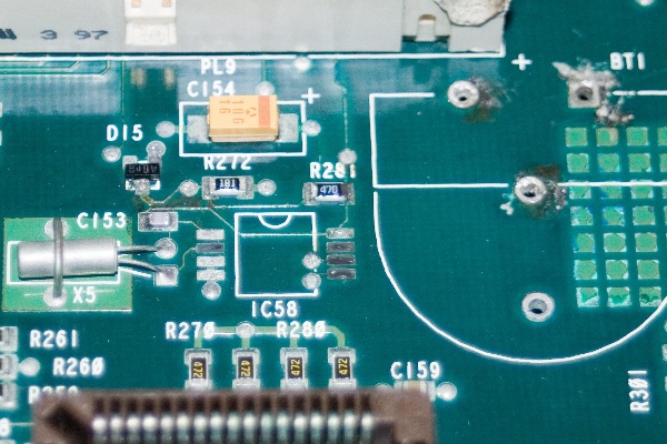
The image below shows the A5000 circuit in the condition it was received in. You can clearly see the gunk and grime build up on the circuit board and damage to the solder pads and tracks wrought by the alkali.
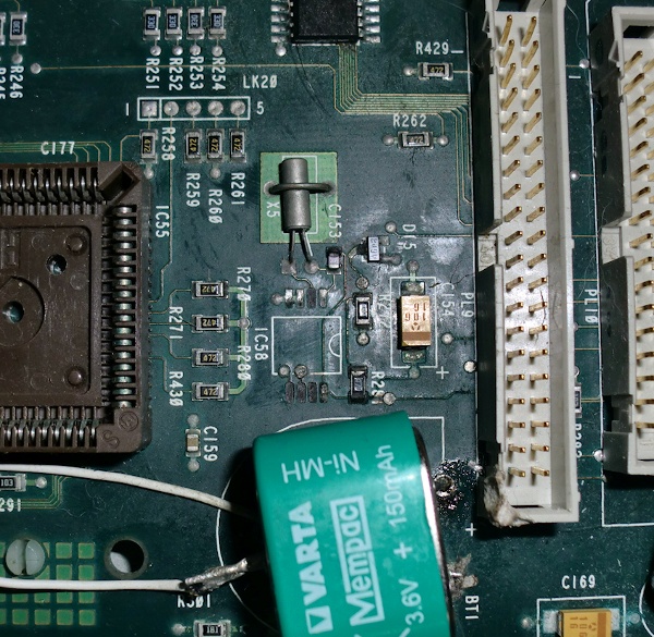
image courtesy Alex (nOmArch)
After removing the battery, cleaning and testing the affected circuitry, the battery charge circuit was found to be good on this particular board despite showing some minor damage to the PCB and so was left in-situ whilst the CMOS/RTC circuit was re-created due to the extensive damage to the solder points where the surface mount CMOS chip should be mounted.
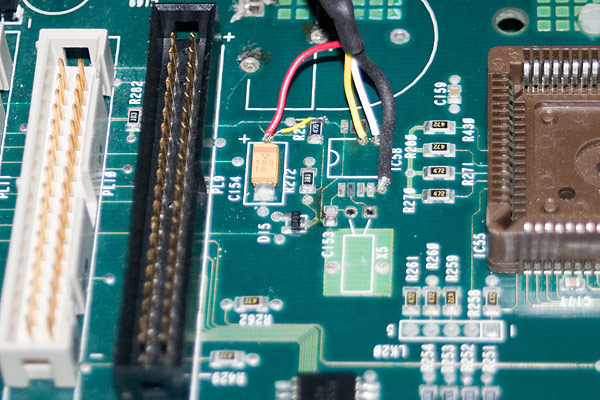
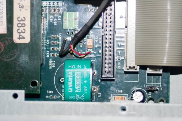
The image below shows the A5000 motherboard with the only track repair that was required and the end of the umbilical cable being soldered into the relevant points to provide connectivity to the re-created circuit. The IDE socket was also replaced due to previous damage.
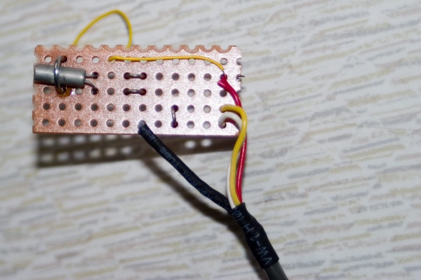
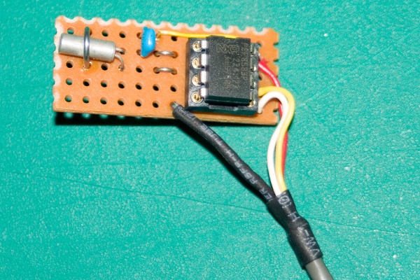
The following image shows the RTC/CMOS circuit part way through its re-creation on TriPad (a variant of Veroboard) with only the 8-way turned pin socket and 15pF capacitor remaining to be added. The image shows parts of the circuit that will be hidden once the rest of the components are fitted.
The CMOS/RTC circuit can then be connected at the other end of the umbilical cable providing connectivity to the small board allowing the CMOS chip and RTC circuit to be powered as normal. You can see in the image below, the original X5 oscillator was salvaged from the motherboard and re-used but all the other components on the board are brand new.
Once the CMOS is connected via the umbilical, the battery can then be re-fitted to the motherboard.
After the board has been repaired, the A5000 is then ready to be used once more. (Video courtesy of Alex (nOmArch) from the Stairway to Hell forums)
Translate this site
Acorn A5000
A5000 Maintenance
POST error calculator
Acorn RISC computer fault codes are reported via the flashing of the floppy drive light in a sequence of 8 blocks of 4 flashes. Each block of four flashes (e.g. long short short long) represents a set of fault and status bits which can be translated into a list of error codes.
Select the boxes that represent the long flashes from your computer to derive the fault code and its translation.
Fault code:
RISC OS - POST values
Common hardware failures
RISC OS links
RISC OS is the operating system that runs on all Archimedes and RISC PC's from Arthur in the beginning, to RISC OS 2 and onwards to RISC OS 4, 5 and 6 today.